MAIN MENU
CATALOG INDEX
BY ALPHABETICAL
ORDER
For more info:
JSi@jsits.com
- [ 8" Ro-Tap Sieve Shaker
]
- [ Brass cloth, brass frame
sieves 8" dia ]
- [ Sieve Shaker for 8", 5"
and 3" Sieves]
Tel:031-479-4211/2
Fax:031-479-4213
DuraLapTest Sieve Shaker DT268J: Built to Take a Beating 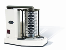
Answering the call for a heavy-duty test sieve shaker, Advantec proudly
offers the DuraLap. With your requirements and budget in mind, this unit
is designed to
succeed where others fail. DuraLap doesn¡ât use typical plastic parts
that wear, so gone are the days of needing to buy ¡°accessory packs¡±
of repair parts for expected breakdowns as some other sieve shakers require.
This industrial-strength unit is engineered with appropriate, rugged steel and alloy materials ready to withstand the everyday, harsh duty cycles. We even provide grease fittings that ensure longer life for your bearings. Each unit is ¡°burned in¡± and run continuously for over half a day, guaranteeing performance right out of the box.
8" (200mm)
Capacity - seven (7) full height; fourteen (14) half height
Dimensions - 28"w x 21"d x 25"h
(71.1cm x 53.3cm x 63.5cm)
Weight - 225lb (102kg) gross
Vertically mounted, enclosed 1/4 hp electric motor.
Built-in digital timer.
The DuraLap Testing Sieve Shaker is designed to give years of trouble-free
service. To assure that the device delivers optimum performance, several
points must be observed before putting the device into service.
1) Mounting Mounting holes for 3/8" diameter bolts Top View For best
results, the unit must be permanently mounted. It is recommended that
unit be bolted to a steel table, heavily constructed wooden bench or other
suitable structure that will be able to withstand the vibratory and hammering
action of the unit. The diagram below shows the location of bolt holes
provided for the mounting. Use 3/8¡± diameter bolts (purchased locally)
to secure the unit. Inspect the mounting periodically for loosening due
to vibration.
2) Cleaning The unit is painted with a baked epoxy finish that will clean
readily with a soft damp cloth. For best results, vacuum any loose particulate
materials prior to wiping the machine clean.
3) Sieve Stack Height Adjustment To assure repeatable and reproducible
results in testing, the drop of the hammer arm has been precalibrated
during assembly. It is essential, however, that the stack of sieves be
installed at the proper height to obtain optimal results. To adjust the
sieve stack height, please observe the following: .Be sure the hammer
lift rod is at the lowest point of travel .Load the stack of sieves, pan,
cover and sieve cover with cork on to the sieve support plate .Loosen
the two wing screws on the sieve support plate .Raise the sieve support
plate along with the sieve stack until the hammer arm comes to an approximately
level position (see diagram) .Tighten the wing screws and begin testing
This unit requires periodic lubrication at two different points in the
mechanism. After every 5 hours of operation, apply any general-purpose
grease containing graphite to the grease fitting at the rear of the top
yoke. At the same time, apply grease to the bulkhead grease fitting located
on the left side of the machine base. Wipe off excess grease before operating.
Do not over apply grease.
Performing a Sieve Analysis using the DuraLap Testing Sieve Shaker
1) Complete installation of the DLap Testing Sieve Shaker per instructions.
2) Plug device into the proper power source (be sure that voltage and
cycle requirements are observed).
3) Prepare the material sample to be tested using industry-specified sampling
and preparation procedures.
4) Select the sieves for the analysis.
5) Assemble the sieve stack, (coarsest sieve at the top, finest at the
bottom) with bottom pan.
6) Pour the sample to be tested onto the top sieve. Install a standard
sieve cover to prevent sample loss.
7) Place the spun sieve cover with cork from the DuraLapon top of the
assembly.
8) Swing the hammer arm up past vertical until it comes to rest.
9) Slide the sieve stack assembly into the DuraLap
10) Adjust the height of the sieve stack assembly and sieve support plate
per instructions. 11) Bring hammer arm back down into place over the sieve
cover.
12) Set the timer for the desired test interval.
13) Upon completion of the test interval, the unit will switch off automatically.
14) Swing the hammer arm up past vertical until it comes to rest.
15) Remove the sieve stack assembly, and proceed to weigh-up the retained
fractions.
Electronic Timer In an effort to make our products even more responsive
to needs of the users, the DuraLapâ Testing Sieve Shaker now features a
digital timer, with greater reliability and precision than most conventional
mechanical timers. Digital Timer The timer controls the cycle time of
the sieving operation, as well as functioning as a 24-hour clock. The
timer and clock setting procedure are described below. Minimum operating
time is 2 seconds, maximum 99 minutes 59 seconds. 1. After applying an
appropriate AC to the power input terminals, the display will be blank
and the beeper will beep for ¨ù second giving the user notification that
the timer is now activated. The units¡â default is in Minute [Mode]. 2.
Setting Time of Day - Push and hold the button [SET/DISPLAY] for 1 second,
the unit will default the time to 12:00am and enter the ¡®Clock Set¡â mode.
While in this mode, buttons [MODE], [STOP] & [START/RESUME] are disabled
and the clock set LED will be turned ON. The user now can set the time
by pressing and holding either [INCREASE] or [DECREASE] button until the
desired time is achieved. If you do not wish to set the time of day, skip
step number 3. The clock mode is a 12-hour with an am/pm display element.
When the clock is being displayed
and the clock is in the pm time frame, the decimal point of number 1-seven
segment will be ON. Once the user has achieved the proper clock value,
they need to exit the clock set mode by pressing and holding the button
[SET/DISPLAY] for 1 second. After the 1 second, the beeper will beep for
1 second giving the user notification that the mode is now exited. Once
the clock is set, the display will go blank and the clock set LED will
turn OFF. If the clock has been set and the user presses the button [SET/DISPLAY]
for less than 1 second, the display will show the current time for a 5
second period and revert back to what was previously on the display. 3.
Setting Interval Timer - In modes 1 . 3, the device functions as a simple
countdown timer. When you set the value, press the button [START/RESUME].
When the value reaches 0, the relay is turned OFF and the beeper beeps
6 sets of 2 (250ms) beeps. Repeat Feature- the timer will remember the
last time set. If you desire to change the setting from the original setting,
press start switch to recall previous setting then input new setting.
To enter one of the 3 countdown modes, press and hold the button [MODE]
for 1 second. Holding down this button the mode will switch every 2 seconds.
Each time the mode switches, the appropriate LED of mode LEDs will be
turned ON and the value displayed will change to the modes default value.
An audible ¨ù beep will also be heard. Mode 1 0 . 99 second: DEFAULT DISPLAY
= 01 Mode 2 0 . 99 minute: DEFAULT DISPLAY = 00.00 Mode 3 0 . 99 hour:
DEFAULT DISPLAY = 00.00 Once the countdown value has been set, you can
now start the timer by pressing the button [START/RESUME]. The relay is
turned ON. While the timer is counting down the user can stop the event
by pressing the button [STOP]. The current countdown value will remain
on the display. If you want to resume the session you just need to press
the start button again. Counting will proceed from the point where stopped.
During this operation, the run LED is blinked at once a second. Once the
timer has counted down to 0 and stopped, you can execute the same session
(time value) by pressing the [START/RESUME] button again. This will recall
the timer value and display it. At this point, you have two options. The
first being the ability to change the value by using the [INCREASE] or
[DECREASE] buttons and the second being the ability to use the same value
and starting the event again by pressing the [START/RESUME] button.
Glass-Calibration-Beads Specification